Anyone who has to do with cams, knows the problem. How to map tables or mechanical cams in a Motion Control system?
For electronic cams controller manufacturers usually provide a so called table mode or simple functions such as sine or polynomial curves.
In table mode the quality of the movement highly depends on the selected interpolation points. Is in the controller linearly interpolated between these points, you need a lot of points to get a good movement accordingly.
The use of sine or polynomial curves has its pitfalls too. Here the quality of the movement depends very much on the skill of the cam designer. Also, by default only polynomials up to degree 7 are available in common motion controllers.
An elegant solution for the problem is converting cam tables and functions into splines. Thus not so many interpolation points are needed in cam tables and any continuous function can be made compatible to standard motion controllers.
Splines take advantage of the fact that they are concatenated segments of polynomials of 3rd, 4th or 5th degree. With cubic splines, consisting of polynomials of 3rd degree, cams can be generated which are continuous in space, velocity and acceleration. With quartic splines, consisting of polynomials of 4th degree, these cams are additionally continuous in jerk. Having quintic splines, consisting of polynomials of 5th degree, the jerks derivative even is continuous.
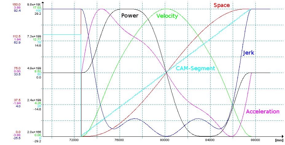
In the oscilloscope picture you can see for example, how a power optimized polynomial curve of higher degree is mapped to a quartic spline in a Jetter Motion Control system completely continuous with 100 cam segments.
It is sufficient that the user specifies only his desired interpolation points. The algorithms of SIMON Modellierungen calculate the corresponding splines automatically.
Moreover, these algorithms in a simpler version are available in JetSym STX. Thus spline curves can be generated directly from interpolation points on a Jetter Motion Control system.

